Application provides great possibilities for developing of different kind of Optical System. You can design and analyze Optical Systems combined with a range of predefined Optical Element, from simple single Surfaces or Lenses to microlens arrays, Fresnel elements, light guides and so on. You can create Optical Element as a combination of Optical Surface and Optical Materials. You can also design your own Optical Element using any kind of CAD software and import it into your Optical Scheme as a triangular mesh.
To create new Element you can either use Insert command of Main Menu or use context menu of Project docked window. In the first case, you will be able to create any Element you want, independently from currently selected type of Element.
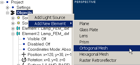
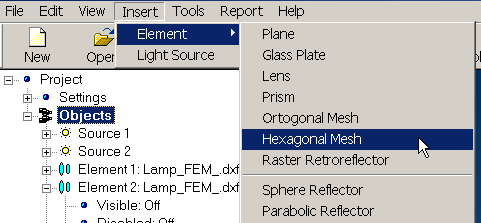
To create new Element using Main Menu:
Note that position of newly created Optical Element within hierarchical tree graph depends on type of element that had been selected before creating procedure. Creating procedure with using Main Menu can be illustrated as below:
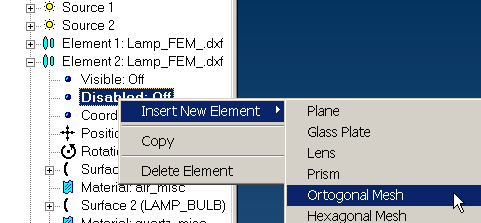
To create new Element using context menu of Project docked window:
Typical cases dealing with creating of new Element are shown below.
|
|
Creating new Element while Object item of hierarchical structure is selected |
|
|
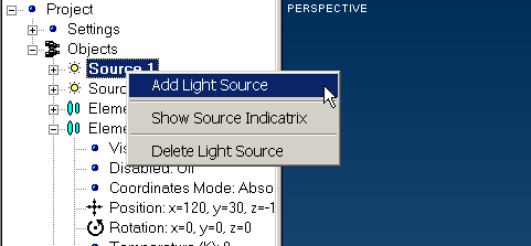
Creating new Light Source while Source item of hierarchical structure is selected |
|
|
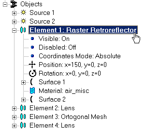
Creating new Optical Element while Element item of hierarchical structure is selected. Note to create new Element you can choose not only Element item itself but also any part of hierarchical structure belonging to that Element. |
Although you can create quite complex Optical Elements using and editing set of predefined Element integrated with Application, sometimes it may be not enough for your purposes. That’s why you can create complex Optical Element as a combination of different single Elements. You can operate then with newly created complex element as usual: move it in arbitrary position, edit properties, create copies, and so on.
To create combined Optical Element:
Typical case dealing with creating of new Element is shown below.
|
|
|
|
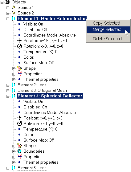
Before combining: two single-surface Elements are selected. |
After combining: Single two-surface Element has been created. Note inherited name of combined object. |
Note you will not be able to separate merged elements.
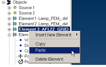
You can create copy of separate Optical Element or group of them within the current Optical System using Clipboard.To copy Optical Elements, select it using context menu of Project docked window, place its copy on the Clipboard, and paste it into Optical System where you want. Before inserting, you can either specify insertion point using hierarchical tree graph or add copied Elements to the end of Project. Note you cannot create a copy of Light Source.
To copy Optical Element:
If it need, you can later edit position of copied Element using corresponding tab in the Properties Docked window.
Typical cases dealing with creating of new Element are shown below.
|
|
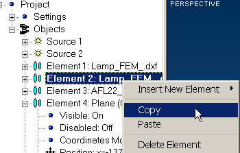
Select single Optical Element and put it into Clipboard |
|
|
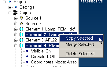
Select group of Optical Elements and put it into Clipboard |
|
|
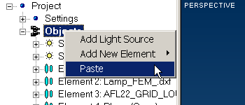
Add copied Optical Element(s) from Clipboard at the end of hierarchical structure of Project |
|
|
Insert Optical Element(s) from Clipboard above selected Optical Element into the hierarchical structure of Project |
You can delete any Element from your project using context menu of Project docked window.
To delete Element:
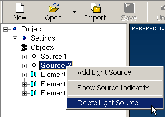
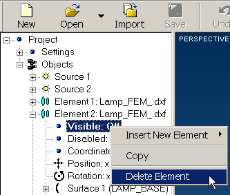
From hierarchical tree graph, choose Element you want to delete. Open context menu and choose Delete Light Source or Delete Element command, depending from what type of Element you want to delete.
Note to delete element you can choose not only Element item itself but also any part of hierarchical structure belonging to those Element.
Typical cases dealing with deleting of Element from Project are shown below.
|
|
|
|
Deleting Light Source |
Deleting Optical Element |
Application provides a great possibilities for investigation of different kind of Optical Schemes using finite-element model representation. You can design some special kind of Elements of Optical Scheme like reflectors or even whole Optical Scheme using any kind of CAD software with following importing of it into your Project. You can also use some library of CAD Objects distributed by third part.
In addition, you can use files created with previous versions of software (*.os format files).
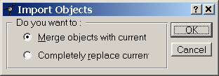
Importing options are available through Main Menu of Application. To be able import objects universal CAD exchange file format (*.dxf) or file format of previous version of Application (*.os) should be used. During import procedure, you will be prompted to choose desired import option (insert Elements into currently used Optical System or replace current Project completely) with Import Objects import shown below:
While you are importing finite-element model represented using CAD format, you will be prompted to choose method of combination of Elements within you Project with window shown below:
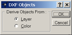
The total number of imported Elements will be equal to number of layers or colors in finite-element model depending on your choice.
All surfaces within imported System will be defined as “Triangular Mesh” type. You can operate with imported Element as usual. The air considered as Optical Material between the surfaces.
You can export you current Project for further developing with any kind of CAD software using universal CAD exchange format (*.dxf). After redeveloping, you can import your results back into Application for following analysis. Exporting option is available through Main Menu. In addition, you can export your project to use it with previous version of Application.
While you are exporting your Project into CAD format (*.dxf), you will be prompted to set desired option for distribution of Elements between different layers:
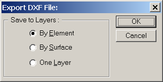
Following options are available:
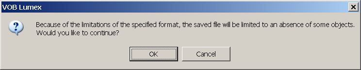
While you are exporting your Project to file format of previous version of Application you will be warned about possible incompability:
To import new Element into Project:
To import new Optical System:
To export Scene: