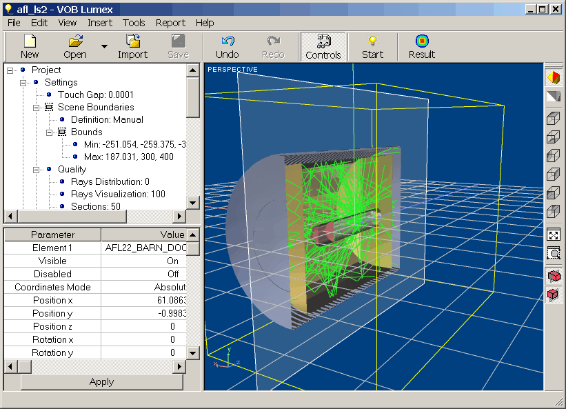
Workspace of the Application software consists of several sections.
An Optical System that you open or create with Application appears in a 3D Viewer window. It provides the survey of whole system or any system part, and some possibilities for system editing. Viewer's commands are accessible through the Viewer's toolbars, Viewer’s context menu, or 3D Viewer submenu of View menu.
You cannot open more than one Optical System in a time, but you can close current Optical System and open or create new one without restarting of Application.
Application commands are accessible through the Main menu bar and Main toolbar placed at the upper part of the application window. Set of operations accessible via toolbar icons covers the most frequently used commands of Application.
As a default, there are two windows providing representation, management, and editing of parameters of analyzed Optical System that are docked at the left part of working area. Project is a top docked window representing a hierarchical structure of the Optical System as a tree of Optical Elements, their components, parameters, and so on. Properties is a bottom docked window that is used for editing of parameters of selected component of Optical System. Both width of docked windows and their mutual height can be changed with using of pointing device at any time.
At the bottom part of main Application window is occupied with Status bar.
Main Menu provides access to the all available commands, modes, and regimes of Application.
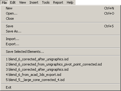
File Menu provides file operation.
|
|
|
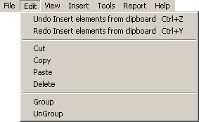
Edit Menu contains commands dealing with editing of Element within your Project.
|
|
|
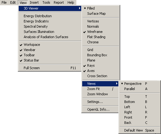
View Menu provides access to the viewing modes of integrated 3D Viewer and to windows responsible for visualization of analysis results
|
|
|
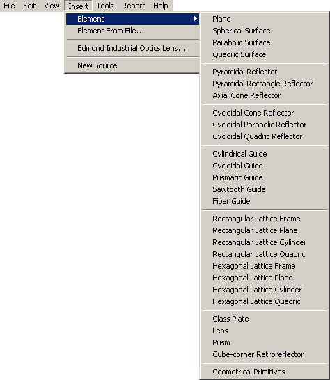
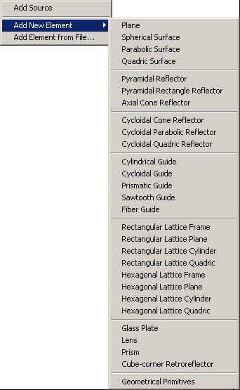
Insert Menu allows you add Elements into your Project.
|
|
|
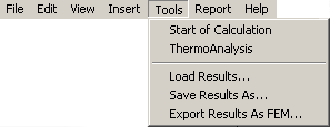
Tools Menu contains command dealing with analysis modes and regimes of Application.
|
|
|
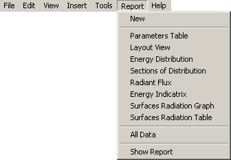
Report Menu allows you to create report containing information about analysis results using MS Excel format.
|
|
|
|
|
– list of components, which can be put into VOB Lumex report. Single user’s selection puts only one component into report. |
|
|
||
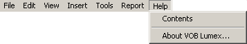
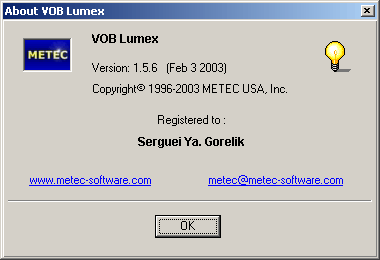
Help Menu provides access to Application reference window.
|
|
|
Main Toolbar provides access to most used commands and regimes of Application.
![]()
The icons are combined in several groups according to their functions.
|
|
New -– Create new optical system |
|
|
Open -- Open existing *.isd file from disk |
|
|
Import – Load finite-element model of optical system saved as *dxf file from disk |
|
|
Save - Save current state of optical system in *.isd format with the same name |
|
|
Undo -– Cancel last editing operation |
|
|
Redo -– Repeat one latest cancelled edit operation |
|
|
Open dialog window to set parameters of analysis plane |
|
|
Start -- Starts calculation of illiminance distribution. While calculations are under executing, the icon is replaced with “Stop” one. Stop -- Stops calculations. |
|
|
Show current state of calculation results of illiminance distribution |
The command operating is described in more details below in corresponding sections of the Manual.
Project docked window represents a hierarchical structure of the Optical System as a tree of Optical Elements, their components and so on. As a default, it is docked at the top left part of working area of Application. Typical view of Project docked window is represented with following illustration:
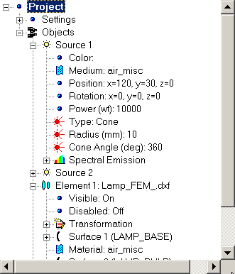
You can use Project docked window to make any Element current and thus available for editing. Selected Element will be marked with blue color as it shown above.
To select Element place pointer over desired title and press left button of your pointing device.
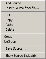
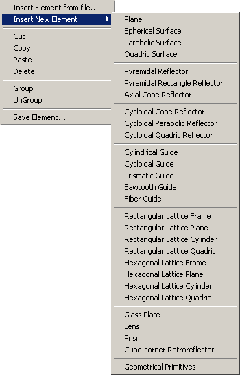
You can use also context menu to add new Optical Element into Project or remove existing one. To get access to context menu select element of Project tree graph and click right button of your pointing device. Content of context menu depends on selected element of Project tree.
Tables below outlines content of context menu available for different type of element of hierarchical tree graph:
|
|
|
|
|
|
|
|
|
Note that context menu depends on the type of currently selected Element of Optical Scheme and does not depend on current position of pointer. Thus, you should select correct type of Element to be sure you will get desired content of context menu.
Project and Settings elements of Project tree graph have no context menu.
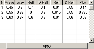
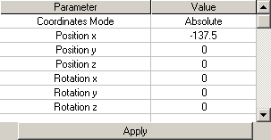
The Properties docked window is used for displaying current parameters characterizing properties either Optical System as a whole or any Element of the Optical System, as well as for setting and changing values of these parameters. Properties docked window is docked at the bottom left part of the working area of Application. The Properties docked window contains a table of parameters and their values and the Apply button. A set of parameters displaying in this window depends on the currently chosen item in the hierarchical structure of the Optical System within the Project docked window.
Examples of views of the Properties docked window are represented with the following illustrations:
 |
|
| View of the Properties window for transformation properties of an element. | View of the Properties window for optical properties of an element's surface. |
To get access to any Property (or group of Properties) of Element, choose corresponding item at the hierarchical structure of Optical System from the Project docked window using your pointing device. All parameters available for editing will be displayed in the Properties docked window. You are able either directly type the desired values of parameters or choose it from drop-down lists in corresponding cells of the table . After new parameters have being set, press the Apply button.