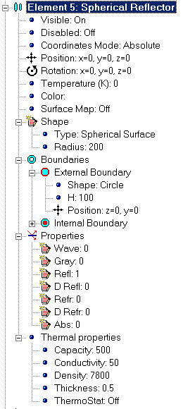
Single-surface Element
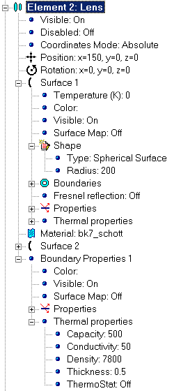
Multi-surface Element
Parameters of each Element integrated into your Project are shown within Project docked window as part of hierarchical tree graph of your Project. Note that parameters defining each item within hierarchical structure (except Element caption) belong to lower level than item itself.
In general, total set of parameters of Optical Element can be grouped as following:
Some set of Properties may be combined into it own hierarchy. Such kind of Properties is marked as group item and expanded or collapsed according to your choice.
Some kinds of Properties are marked with specific icon to make understanding more intuitive.
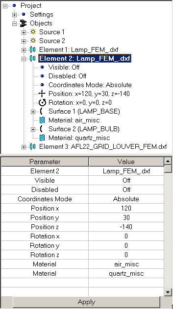
Typical structures of Element properties set for single-surface and multi-surface Elements are shown below:
|
|
|
|
Single-surface Element |
Multi-surface Element |
While any expandable/collapsible group of items have been selected, corresponding properties will appear in the table at Properties docked window. You can also select single property to display it at the Properties docked window. Contents of the group or separate property currently available for editing is marked with blue color. List of editable parameters is shown at the editable table of Properties docked window.
Typical view of Properties table is shown below:
|
|
|
|
|
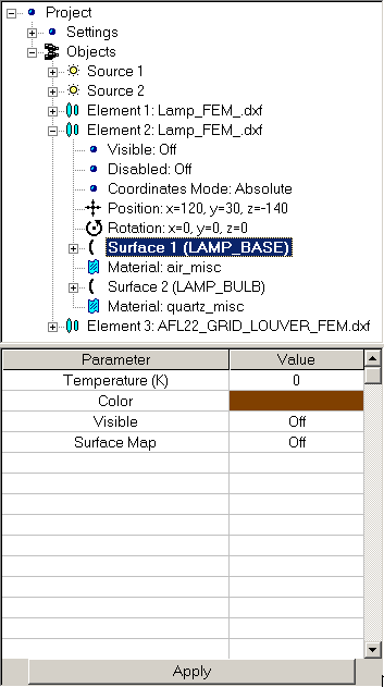
List of Optical Element properties |
List of collapsed group of properties |
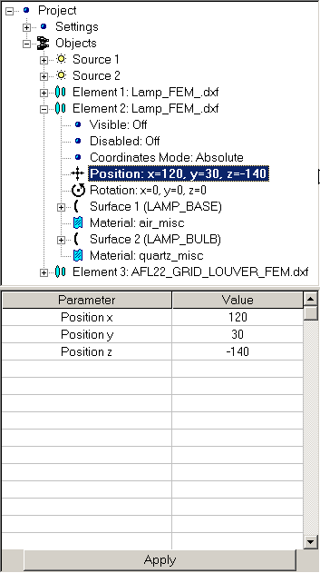
List of separate property |
Note that just properties directly placed at the corresponding hierarchical level are listed at the table while properties belonging to group of lower hierarchical level are not appeared. You don’t need to expand hierarchical group to get access to its properties; it’s enough to select it.
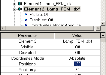
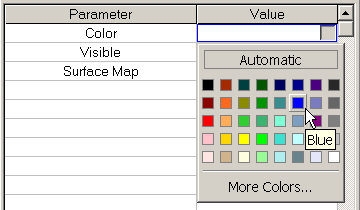
Table of properties consists of two columns: Parameter containing caption of parameter and Value used for parameter editing. Except some special cases, you can either edit parameter directly or choose desired parameter value from drop list. Both cases are illustrated below:
|
|
|
|
Edit parameter directly |
Choose value from list |
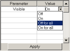
After new value have been entered press Apply button at the bottom of Property table.
Depending your current needs, you can hide or show any Element of your Project to provide more understanding of Optical System structure. In addition, you can change visualization color of Element to create more attractive visualization result.
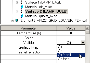
To turn on or turn off visualization of Element:
Following Visible options are available to be used:
|
|
|
Note you can hide or show not only Element as a whole but some part of Element, for example, some Surface, Boundary, and so on. Hiding of Element will not affect analysis of Optical System.
To change visualization color of Element:
From hierarchical tree graph, choose Element you want to hide or show, or choose Color parameter of that Element directly using your pointing device.
Within Properties docked window, choose Color value and open table of color using button at the right side of Color value field. Choose desired color. You may also choose Automatic option to allow Application choose color automatically or customize color using More color option.
Figures below illustrate above described procedure.
|
|
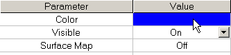
Choose Color value |
|
|
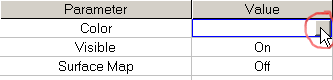
Click button at the right side of Color value field. |
|
|
Keeping first button of your pointing device pressed, choose color you want to apply. |
Positioning of Optical Element is defined with two independent properties: Position and Rotation. Position group defines location of Element according to currently selected Coordinates Mode (see Cartesian Coordinate System for reference) while Rotation property is responsible for orientation of Element within 3D space (see Tilt Coordinate System for reference).
Both properties are combined into Transformation group within hierarchical tree of Optical Element as it shown below:
|
|
To get access to Position and Rotation properties:
Choose Transformation group of properties.
Immediately after it, whole set of parameters defining location and orientation of Element will be available with Properties docked window. Nevertheless, you can expand Transformation group and choose desired property directly.
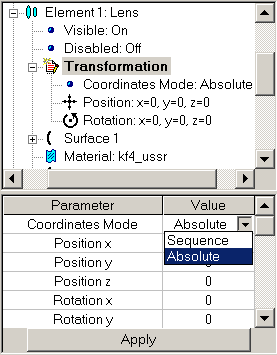
You can switch between modes anytime you want. Coordinate mode property is used for this purpose.
To set desired coordinate mode
To get access to Coordinate mode property, within Project docked window, choose any Element.
Choose Transformation group of properties.
Within Properties docked window, set desired coordinate mode.
Although whole set of parameters defining location and orientation of Element will be available with Properties docked window after Transformation hierarchical group have been chosen, you can expand Transformation group and choose Coordinate Mode directly.
Note your changes will affect all Elements combined into Optical System. Example of Coordinate mode setting is shown below:
Besides differences dealing with definition of coordinates of Element of Optical Scheme, currently selected Coordinate Mode will affect position and orientation of all following Elements within hierarchical tree of Optical System.
Six cells “Value” of “Position” and ”Rotation” rows represent editable fields, where real numbers – the coordinate and rotation angle values should be typed to change element location. Under pressing “Apply” button the new values are accepted and system layout is renovated immediately. In case the newly typed cell contents cannot be decoded as real number, its previous value is used.
To set location of Element:
You can change orientation of any element of your Project, and even whole Optical System.
Generally, to change orientation of any part of your Project you have to specify angle of it's rotation using Properties docked window. Each element of hierarchical structure of your Project has Rotation properties defined as a set of three values defining current angle of rotation of element around axes of cardan joint containing bounding box of element with respect to pivot point of element itself. See Polar Coordinate System for reference.
Note that Scene as a whole has now Location tab. To get access to Scene Rotation property it is enough to choose Scene within hierarchical structure of Project.
To set orientation of single element:
To rotate part of Optical Scheme:
defining positions of surfaces in complex element in “Absolute” mode
User’s work with tree makes it clear whether the keyword “Absolute”/“Sequence” refers to an element or to a surface.
You can change form-factor of any Element redefining parameters responsible for its shape. Corresponding parameters are combined into Shape group of properties of hierarchical tree graph of Element.
To change form factor of Element’s shape:
Clear Aperture is property of Surface describing open light zone providing ray transformation. Some optical elements like single- and double-surfaces, reflectors and so on require direct definition of its clear apertures.
You can define both external and internal boundaries of clear apertures. Working area of Element lies within the external boundaries but outside of internal ones. Shapes of both external and internal boundaries can be specified independently.
Clear Aperture properties are combined into Boundaries group of hierarchical tree that belongs to one level below Surface Element. In turn, External and Internal Boundary are hierarchical groups within Boundaries level.
The example of fragment of tree graph containing Clear Aperture properties hierarchy is shown below:
|
|
|
Note that Clear Aperture property is defined not for all Optical Elements.
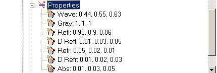
Optical Properties of Element define refraction and reflection properties of Element. As a default, it is assumed that Optical Properties are constant throughout whole surface and independent of wavelength. Nevertheless, you can define spectra diagram of each properties.
Like Clear Aperture, Optical Properties are combined into Properties group of hierarchical tree one level below described Element to define properties of Surface. In contrary to Clear Aperture, Optical Properties are part of hierarchical structure of any Optical Element within your Project and define lowest Elements of object’s hierarchy.
The example of fragment of tree graph containing Clear Aperture properties hierarchy is shown below:
|
|
|
Note that sum of all coefficients for each wavelength should be equal to unit value.
Optical Properties of Element boundaries (if applicable) are also combined into corresponding hierarchical group (Boundary Properties). You can define it in the same manner.
Gray property is dealing with thermal properties of Element it is combined into group of Optical Properties because just surfaces can be considered as thermal sources within Application.
To set optical properties of Pyramidal Reflector’s surface:
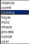
With Application, you will get access to set of optical materials provided by most significant manufactures, such as Schott, Corning, O’Hara, Hoya and others. You cannot edit directly optical properties of chosen Material (like refractive index and so on) but you are able to choose suitable Optical Material from catalogue. Optical properties need for analysis purposes will be used according to wavelength defined in Light Source section.
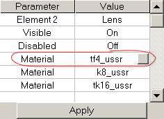
Name of Optical Material consists of two parts: right part contains brief name or abbreviation of catalogue while left part contain name of material within catalogue. As an examples, tk4_ussr denotes TK-4 glass chosen from USSR catalogue.
Full list of available catalogues is shown below:
 |
|
To get access to Optical Material catalogues you have to use button appearing at the right part of row containing currently editing Material as it shown below:
To change Optical Material
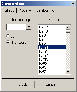
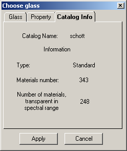
The cell “Value” of the “Material” row represents text reference field together with hidden button, which, if being pressed, opens dialog window of changing optical transparent material. The dialog window contains three bookmarks: Glass, Property, and Catalog Info.
The situation appears to be just the same in case the “Material” row is not single one in the table, but represents one of the constituents of “Element” parameters:
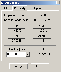
Bookmarks of “Choose Glass” dialog window:
|
|
|
|
|
where: nl -– refractive index for selected wavelength. nF -– refractive index for 0.4863 micron vawelength, nC -– refractive index for 0.6563 micron wavelength.
P -– Relative partial dispersion calculated as
Density -– material density as grams/cm3
|
|
|
Bookmark contains reference catalog info |
Pressing “Apply” button puts selected glass (material) to its place in the optical element.
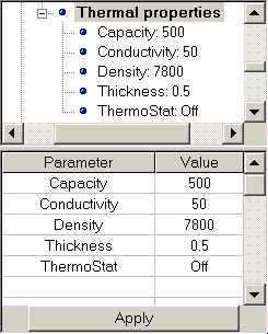
Thermal properties are next general group of properties of Optical Element. Most of Thermal Properties are combined into Thermal Properties group.
The example of fragment of tree graph containing Clear Aperture properties hierarchy is shown below:
|
|
|
In addition, you can specify emissivity factor (see Optical Properties for reference) and initial temperature of Element.
To set thermo properties of Element’s surface: