General Settings
Before starting of analyzing procedure, you should define some set of general
parameters affecting analysis precision and visualization of analysis results.
Then, some starting conditions should also be defined.
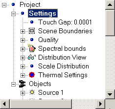
For this purposes, Settings group of properties is used. It is first
level hierarchical group within project tree graph containing several subgroups.
General view and brief description of general settings are shown below:
Set of Scene Boundaries parameters defines bounding box that will be
taken into account during analyzing procedure. All Elements of Optical Scheme
that may be represented with triangular mesh are included into scene boundaries.
If trajectory of ray passed through the Optical System will reach boundary of
bounding box this ray will be excluded from following analysis. At the same
time, you may place your light sources outside scene bounding box. In any case,
you have to make sure all light sources are placed within scene boundaries and
oriented correctly.
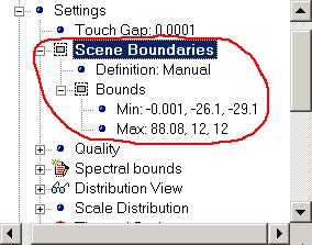
Hierarchical structure of Scene boundaries properties group are shown
below:
|
- Definition -- Type of definition of Scene Boundaries (Auto or
Manual).
- Bounds -- Subgroup of properties defining boundary corners of
Optical Scheme bounding box.
- Min -- Coordinates of lower corner of bounding box (x, y, z).
- Max -- Coordinates of upper corner of bounding box (x, y, z).
|
You can set Scene Boundaries manually or in automatic mode. While you
are using automatic mode, minimally required bounds to include whole system in
current configuration will be set to include all Elements of Optical Scheme into
resulting bounding box. You will not able to change bounds manually (although
you will be able to get access to corresponding values).
Otherwise, while you are use manual mode of boundaries settings, you may set
bounds of your Optical Scheme to certainly exceed currently required external
dimensions of bounding box. It can be useful when you are working win Optical
System having moving parts. In this case, you will be released from warnings
appearing with each system reconfiguring.
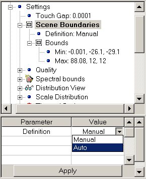
Examples of setting parameters dealing with definition of Scene Boundaries
are shown below:
 |
 |
| Setting of Definition Mode |
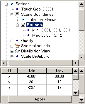
Setting of Optical Scheme bounds manually |
To change definition mode of boundaries settings:
- Within
Project docked
window, expand Setting group of parameters within
hierarchical tree graph and choose Scene Boundaries group.
- Within Properties docked
window, choose desired definition mode from list.
- Press Apply.
- To set Scene Boundaries manually:
- Set Definition mode to Manual.
- Within hierarchical tree graph, expand Scene Boundaries group of
parameters and choose Bounds subgroup.
- Within Properties docked
window, set desired bounds of Optical Scheme
- Press Apply.
Note you are not able to set bounds in so manner to exclude part of Optical
Scheme from resulting bounding box.
Set of Quality parameters allow you to control analysis accuracy. Set
of parameters can be illustrated with table below:
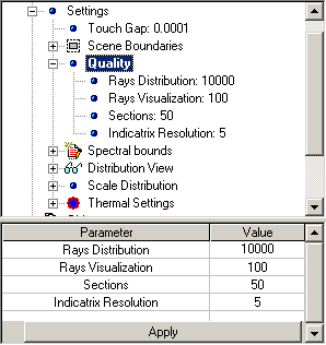 |
- Rays Distribution -- Total amount of rays generated until
analysis procedure will complete. Zero value corresponds unlimited rays
generation for illumination analysis purpose and 500,000 rays for thermal
analysis purposes..
- Rays Visualization -- Amount of generated rays to be visualized
with 3D Viewer. Affect only visualization part.
- Sections -- Amount of layers parallel each side of bounding box
defining accuracy of analysis of spatial distribution of energy. See
Energy Distribution for reference.
- Indicatrix Resolution -- Angular resolution of polar diagram of
energy distribution of radiant intensity (W/str). See Energy Indicatrix
for reference.
|
Energy Composition parameter may accept following values:
- None -- Nothing will be displayed in analysis plane
- Direct Light -- Only radiation coming to the surface directly from
the source(s) is added to the result.
- Indirect Light -- Only reflected radiation coming to the surface is
added to the result.
- Direct and Indirect Light -- Both direct and reflected radiation
components coming to the surface are added to the result.
Spectral Bounds property defines what part of spectrum emitted with
all Radiation Sources will be taken
into account during calculation and analysis procedures. Set of parameter can be
illustrated with table below:
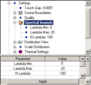 |
- Lambda Min -- Wavelength defining lower bound of used spectral
range.
- Lambda Max -- Wavelength defining upper bound of used spectral
range.
- N Lambda -- Total amount of subdivisions of used spectral
range. Affects on accuracy of analysis
|
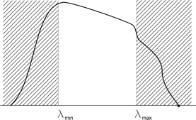
Note that Spectral Bounds property does not concern with
Spectral Emission property of
Radiation Sources. It can
be illustrated with figure below:
Set of Distribution View parameters allow you to control
representation of analysis results dealing with spatial distribution of energy
within Optical Scheme. Set of parameters can be illustrated with table below:
 |
- Surface Map -- Currently displayed Surface Map. See Surface
maps for reference.
- Energy Composition -- Currently displayed part of energy
contributed into spatial energy distribution. See Energy Distribution
for reference
- N intersect. Min -- Minimal count of intersection between ray
and surface of Optical Element will be considered as essential for result.
- N intersect. Max -- Maximal count of intersection between ray
and surface of Optical Element will be considered as essential for result.
- E rel Min -- Minimal level of resulting signal range will be
represented. Relative value.
- E rel Max -- Maximal level of resulting signal range will be
represented. Relative value.
- Energy Threshold -- Minimal level of ray weight that will be
considered as essential for result. Relative value.
|
Energy Composition parameter may accept following values:
- None -- Nothing will be displayed in analysis plane
- Direct Light -- Only radiation coming to the surface directly from
the source(s) is added to the result.
- Indirect Light -- Only reflected radiation coming to the surface is
added to the result.
- Direct and Indirect Light -- Both direct and reflected radiation
components coming to the surface are added to the result.
To set desired Distribution View Settings:
- Within
Project docked
window, expand Setting group of parameters within
hierarchical tree graph and choose Distribution View group.
- Within Properties docked
window, choose from list desired options for Scale, Units,
and Interpolation parameters.
- Press Apply.
Note you have to stop analysis procedure before changing setting of
parameters within Distribution view section.
Before new values of parameters (except E rel parameter) will affect,
you have to restart analysis procedure. Changing E rel parameter will
also affect representation of analysis result without recalculation.
Set of Scale Distribution parameters expand control possibilities
dealing with representation of spatial energy distribution. Set of parameters
can be illustrated with table below:
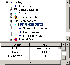 |
- Scale -- Allow you to choose reference level for normalization
of energy map.
- Units -- Allow you to set currently used scale of
representation of energy map.
- Interpolation -- While turned on, interpolation will be used to
smooth energy map representation.
|
Scale Distribution parameter may accept following values:
- Auto in Section -- Energy Distribution map will be normalized with
respect to maximum energy level within currently chosen section.
- Max in Volume -- Energy Distribution map will be normalized with
respect to maximum energy level within bounds of Optical Scheme.
To set desired Scale Distribution Settings:
- Within
Project docked
window, expand Setting group of parameters within
hierarchical tree graph and choose Scale Distribution group.
- Within Properties docked
window, choose from list desired options for Scale, Units,
and Interpolation parameters.
- Press Apply.
You can change setting of any parameter within Scale Distribution
section during analysis procedure. Changes will be applied immediately.
Set of Thermal Settings parameters describes general options affecting
results of thermal analysis of Optical System. Set of parameters can be
illustrated with table below:
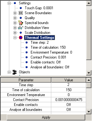 |
- Time Step -- Minimal time discrete to be analyzed.
- Time of calculation -- Time (in the terms of simulated system)
to finish thermal analysis routine.
- Environment Temperature -- Temperature of environment of your
System.
- Contact Precision -- Minimal allowed distance between points of
System Design considering as different ones.
- Enable contacts -- While turned on, heat exchange between
contacting elements is allowed
- Analyze all boundaries -- While turned on, all boundaries of
each Element of Optical System will be analyzed.
|
To set desired Thermal Settings:
- Within
Project docked
window, expand Setting group of parameters within
hierarchical tree graph and choose Thermal Settings group.
- Within Properties docked
window, set desired values of Environment Temperature and
Contact Precision properties.
- Within Properties docked
window, choose from list desired Enable contacts and Analyze all
boundaries options.
- Press Apply.