To specify position and center of rotation of Elements within your Project Pivot Point term is defined. Pivot Point is imaginary point used to specify both location of Element within three-dimensional (3D) space and center of rotation of Element. In other words, position of Element is position of Pivot Point of Element; rotation of Element will be applied around Pivot Point of Element. Therefore, while you are defining position of Element you are entering coordinates of Pivot Point of Element with respect to used Coordinate System. While you are defining orientation of Element you are defining angles of inclination of Element around Coordinates Axes with respect to center of rotation placed at the Pivot Point.
Note you are not able to change position of Pivot Point of any Element of your Project.
For Elements that are represented with set of analytical surfaces, Pivot Point belongs to top point of first surface of Element.
For imported CAD element position of Pivot Point will be defined with position of coordinate system origin within CAD file.
Note each surface combined into complex Optical Element has its own internal pivot point. With it, you can change location and orientation of each surface within complex Optical Element independently from other ones.
Right-handed Cartesian Coordinate System is used to specify location of Optical Element at three-dimensional space. It is usual three-axes coordinate system. Coordinate values indicate a distance (in units) and its direction (+ or -) along the X-, Y-, and Z-axes relative to the Coordinate System Origin (0, 0, 0). As a default, the X-axis is Optical System Axis, the Y is vertical, and the Z-axis is perpendicular to X0Y plane.
You can use two methods to specify position of Optical Element – Absolute and Sequence modes of positioning.
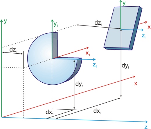
With using of Absolute mode, position of each Optical Element is defined with respect to the same origin. As a default, origin of Absolute (Global) Coordinate System belongs to first surface of Optical System. Following illustration demonstrates general principles of the location of Optical Element at 3D space using Absolute positioning mode. You specify X, Y, and Z values of the coordinate of Optical Element with respect to common origin of Coordinate System.
Note that position of Light Sources is always defined with using of Absolute mode of positioning.
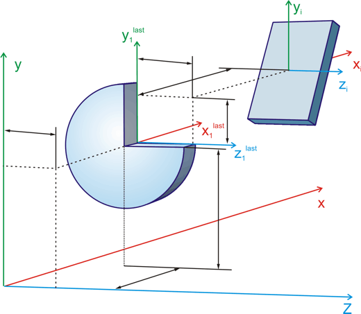
With using of Sequence mode position of each Optical Element is defined with respect to the last surface of previous Optical Element. In other words, you have to define position of currently selected Element with respect to origin of the local Coordinate System placed at the last surface of previous Element (accounting it's orientation with respect to Global Coordinate System). Following illustration demonstrates general principles of the location of Optical Element using Sequence positioning mode. You specify X, Y, and Z values of Element with respect to origin placed at the first surface of previous Element.
Tilt Coordinate System is used to indicate inclination angles of Element (in degrees) and its direction (+ or -) around the X (Gamma -- g), Y (Beta -- b), and Z (Alpha -- a) axes relative to the Pivot Point of Element itself. Rotating of Element is realized as it is integrated into gimbal as it shown on figure below:
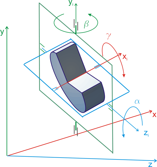
Note all axes of gimbal cross at the Element's pivot point. Y axis of Tilt Coordinate System is already codirectional with Y axis of Global Coordinate System; Z axis of Tilt Coordinate System is rotatable within X0Z plane.
Sequence of rotations around different axes is crucial. So, if you want to set orientation of Element according to preliminary known angles a0, b0, and g0, you should first set orientation around X axis, then around Z axis, and finally set orientation around Y axis.
Like Cartesian Coordinate System, both Absolute and Sequential modes are available to specify tilt of Optical Element. In the first case, rotational angles will be defined with respect to axes of global Coordinate System. Otherwise, angles will be specified with respect to local Coordinate System placed at the last surface of previous Element (accounting it's orientation). So, in this case, entering rotation angles for Element, you will be specify it's orientation with respect to previous one.